1 Introduction
Non-contact smart card technology is a new multi-disciplinary and multi-disciplinary technology that integrates radio frequency identification and wireless communication in recent years. It uses wireless communication technology for contactless two-way communication to achieve the purpose of exchanging data and has no contact. A series of advantages such as large working distance, high precision, fast information processing, and good environmental applicability n], its birth will accelerate the informationization of people's lives. The contactless smart card reading and writing system is an important part of the technology, and can complete many functions such as command analysis and data acquisition.
Since the previous code reading and decoding unit of the reading and writing module is separated from the RF transceiver unit, the RF transceiver unit must be developed separately, which brings disadvantages such as long development cycle, poor system stability, high production cost, and difficulty in maintenance, thereby making it Full promotion of applications has been limited. This paper proposes a design scheme based on MFRC500, which is highly integrated with the RF transceiver unit. It overcomes the above-mentioned shortcomings and has the advantages of small size, low cost and easy maintenance. In addition, due to its good electromagnetic Compatibility, system stability, and communication reliability are strongly guaranteed.
2 Module working principle
The contactless smart card reading and writing module is mainly composed of two parts: a reader/writer and a smart card. The smart card is also called a radio frequency card. The data is exchanged between the reader and the card through radio induction. The radio signal sent by the reader base station is generally composed of two. Part of the composition: energy and data. After receiving the energy signal of the fixed frequency, the RF card generates resonance by the LC loop that it carries, and is rectified, filtered, and stabilized by the subsequent single-pass electronic pump to generate an instantaneous energy for the IC on the chip. After the card receives the data, the on-chip IC interprets and executes the instruction data information, completes the data modification, storage and other operations and returns the execution result to the reader/writer. The entire system does not need to be touched, and the data information transaction is fast.
3 system design
A typical smart card reader system should consist of at least two parts: a reader and a smart card. In the reading and writing system, the reader functions as a base station and the smart card acts as a terminal. The two establish a wireless link from the RF field to complete data exchange. In addition, in order to ensure the security of the data, in this design, the MiFare One smart card is adopted, and the data streams are all encrypted transmission. The hardware design block diagram is shown in Figure 1.

Figure 1 system block diagram
Among them, the single-chip microcomputer receives the instruction sent by the PC through the serial port and is responsible for the interpretation of the instruction, completes the operation of the card and the management of the module itself, and the MFRCS00 is responsible for the encoding and decoding of the signal, the modulation and demodulation of the radio frequency signal. The matching circuit and filter are responsible for making the internal frequency front end circuit of the MFRC500 and the antenna reach a good match and filtering out the higher harmonic components. The design of this part can affect the output of the RF power and the anti-interference ability of the system. The RF oscillating energy signal is converted into electromagnetic waves and radiated into the air. The MiFare One card is an application terminal of the module, receives the command and sends the command execution result.
3.1 Data encoding and decoding form
The half-duplex communication method between the reader (referred to as PCD) and the MiFare One card (PICC for short). PCD is used as the base station and PICC is used as the intelligent terminal. In order to realize the reliability of data communication and meet the requirements of other functions of normal communication, the system adopts appropriate coding and decoding and its modulation and demodulation methods.
3.1.1 Downlink Data Link
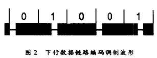
The downlink data link refers to the data link from the PCD to the PICC. The PCD actively sends commands and the PICC passively responds. The data transmission rate in the link is 106 kbps, and the data coding is performed by Modified Miller. After being modulated by the carrier frequency 13.56 MI-Iz to the radio frequency with 100% ASK, it is sent through the PCD antenna. The coded modulation waveform is shown in Figure 2.

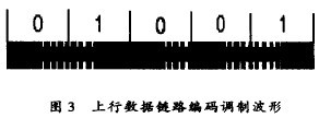
3.1.2 Uplink Data Link The uplink data link refers to the data link from the PICC to the PCD. The PICC sends the command execution result. The PCD receives the execution result and performs corresponding processing. The data transmission rate in the link is 106 kbps, and the data coding is performed by Manchester. After being modulated by the carrier frequency 13.56MI-Iz with 100% ASK to the radio frequency, it is sent out via the PICC antenna. The coded modulation waveform is shown in Figure 3 [2].

3.2 module key circuit design
The hardware module is mainly composed of a single-chip microcomputer, MFRCS00, matching circuit, antenna and corresponding peripheral circuits. Among them, MFRCS00 is used as a base station chip to complete all tasks such as encoding and decoding, modulation and demodulation, power amplification, etc. The most critical of the system is also positive. It is the design of the base station chip and its subsidiary circuit, and the design is shown in Figure 4.
The base station chip has an EPP function, which automatically detects the interface mode after power-on. In many of its interface modes, we use the Separrated Read/Write Strobe mode. In Figure 4, NCS is the chip select line and is also part of the address line. Because of the Separrated Read/Write Strobe mode, A0 and A1 should be low and A2 should be high for normal operation; DO?I 7 is the data/address line; ALE is the address latch line; NRD/NWR are the read/write lines respectively; IRQ is the output end of the base station chip generating the interrupt signal, which is processed by the MCU as an external interrupt request; RSTPD is controlled by the MCU Next, the initialization process of the chip is completed; TX1 and TX2 are the outputs of the on-chip RF power amplifier, and the modulated energy signal is fed into the antenna through the filter and the matching circuit, and the antenna is converted into electromagnetic waves to radiate into the air.

Figure 4 base station chip circuit design
3.3 Module software design
Since the module works under the supervision of the PC, the master-slave communication mode is used between the two. After the module is powered on and completes the normal initialization process, it enters the wait state and waits for the command sent by the PC. When the module detects the valid command of the PC, it goes to process the corresponding program, and after the processing is completed, the execution result status information is returned to the PC. The software flow chart is shown in Figure 5.
4 test results
4.1 Module key instruction test and analysis
In the experiment, in order to verify the reliability of the module work, the key instructions of the module were tested several times. The test results are listed in Table 1.

The above is the test result of the six instructions after the Mfare One card Authentication. The test results show that the command success rate has reached 100% in a limited number of tests. It can be seen that the module has good electromagnetic compatibility, meets the requirements of system stability and communication reliability, and lays a foundation for its practical application.
4.2 Human-computer interaction interface
In order to facilitate debugging, a simple and practical human-computer interaction interface has been specially written. Figure 6 shows the results of a certain debug command run.
5 Conclusion

Figure 6 Human-computer interaction interface
The RF card reading and writing module developed in this paper adopts the advanced technology of Philips, and selects MFRC500 with high integration characteristics as the base station chip. It has good electromagnetic compatibility, communication is more stable and reliable, and realizes the reading and writing module and MiFare One card. Between the wireless communication, all the instructions have been debugged, the read and write distance can reach 8cm, and can be further improved. Practice has proved that the performance is stable.
Ningbo Smile tools Co.,ltd , https://www.nbsmiletools.com