Research on the Process of Bucket Flanging at Home and Abroad
Yang Wenliang Xin Qiaojuan
The steel barrel barrel burring process is an intermediate preparation process for steel drum assembly molding, which directly affects the quality of the steel drum finished product, and is one of the most important processes in the production process.
There are many methods for burring the barrel at home and abroad. Generally, it can be classified into three types, namely, mold flanging, rolling cuffing and bulging cuffing. In the domestic barrel industry, rolling and flanging is more common, and the modern barrel production line mostly uses mold flanging and bulging.
First, the mold flanging
As shown in Figure 1, it is a schematic diagram of the working part of the mold flanging. This flanging method is generally hydraulically driven and can be automated. Firstly, the hydraulic body (or pneumatic) dial mechanism is used to pull the barrel into the initial position in the flanger, and then the die top rod moves to the middle under the action of the hydraulic cylinder. When the head of the stamper enters the edge of the barrel, the cone is inclined by the pressure plate to face the barrel body, and the position of the mold is advanced to the middle to clamp the barrel, and then the edge of the barrel is under the action of hydraulic pressure. When the width of the flange is up to the process requirement, the edge of the barrel is pushed up by the limit step of the outer ring of the die, and the displacement of the die is greatly resisted. When the stamper is subjected to resistance, that is, when the hydraulic pressure reaches the set pressure, the electromagnetic reversing valve is reversed, and the hydraulic cylinder returns, so that the stamper is quickly withdrawn from the inside of the barrel. The bucket device immediately pulls the overturned bucket out of the flanger.
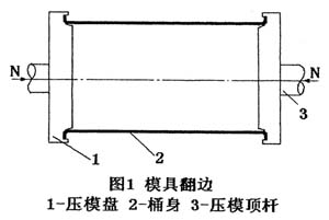
The main advantages of mold flanging are high efficiency, good quality, simple structure and small size.
The use of hydraulic transmission not only reduces the mechanism, but also gives the flange a greater force. More importantly, the degree of pressure is used to adjust the degree of cuffing of the barrel, so that each barrel, regardless of the length of the barrel, the width of the cuff is always guaranteed. If the mechanical transmission is adopted, since the transmission position can only be set to a common value, since there is always a certain deviation in the length of the barrel body, a satisfactory flanged effect cannot be obtained, and defects such as insufficient or excessive width of the flange may occur. .
The disadvantage of the mold flanging is that the transition arc angle of the flanging is too large, because the rounded corner is too small to feed, so the molding is difficult, and the resistance is large, and the arc portion of the stamper is easily damaged. In addition, due to the rebound, the angle between the flange and the barrel is not easily turned into a right angle, generally between 95 ° and 120 °.
Figure 2 shows the simplified hydraulic system schematic diagram of the mold flanger. When the flange pressure reaches a certain set pressure, the pressure relay 2PD operates, that is, the electromagnet 2DT operates, so the three-position four-way reversing valve reverses, so that the hydraulic cylinder returns, and when it moves to a certain position, it hits the bucket stroke. The switch, so that the drum stroke relay is energized, drives the drum mechanism to dial the bucket, and the dial barrel mechanism is reset and then hits the bucket bucket stroke switch action, even if the electromagnet IDT is operated, the reversing valve is reversed, and the hydraulic cylinder enters the work again. status.

The above is a brief introduction to the working principle of the hydraulic drive mold flanger. In Figure 2, only the main working circuit liquid recognition drive mode is easily realized.
Second, rolling flange
Figure 3 shows the working diagram of a typical roll forming machine. As shown in the figure, the upper and lower rollers are placed on the side of the barrel, and some of the cuffing machines place the upper and lower rollers under the barrel to perform the cuffing.
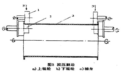
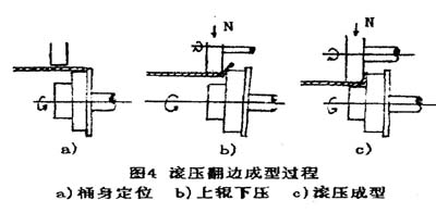
Figure 4 shows the working process of rolling and flanging. a) The figure is that the barrel blank is placed on the first step of the lower roller for positioning before forming, in order to make the barrel body not move left and right and affect the accuracy of the flange, the left and right rollers have a limit step on the left and right rollers, so that the barrel body Just caught in the roller. b) The drawing is the working stage, the upper roller is pressed down, and the barrel body is in contact with the barrel body, and the barrel body is rotated together with the upper and lower rollers. During the process of pressing the upper roller into the lower feeding, the barrel body is simultaneously lowered with the upper roller, and the barrel side is on the upper and lower rollers. The gap is turned outwards. c) The picture shows the end of the rolling process. As the upper roll continues to fall, the barrel is pressed down to the lowest roller step, the flange is basically formed, and enters the shaping stage. After a period of shaping, the cuff ends. The upper roller rises.
Generally, in large-volume production, the lower roller should be placed on the inner side of the lower part of the barrel, and the upper roller should be placed on the outer side of the lower part of the barrel to facilitate automatic production. The drum can be placed under the barrel and the bucket and the lower barrel can be placed at any time.
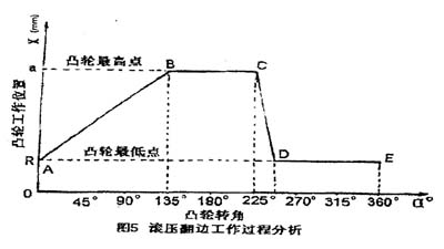
The upper roller pressing action is generally realized by the cam slider mechanism, and also works with the cylinder, but the cylinder movement is not accurate, so there are many cam mechanisms in the country. The downward movement of the upper roller should be divided into three phases, namely, the downstream phase, the stagnation and pressure holding phase, and the upward idling phase. Figure 5 shows the working process of the cam rotation one week. The analysis is as follows:
The AB section is the cam pressing stage, and the working radius of the cam is rising. At this time, the cam is turned from the lowest point to the highest point, and the upper and lower rolls are gradually pressed. When the point B is reached, the flange is basically formed.
The BC section is the cam holding phase, and the BC section is on the cam with the rotating shaft as the center of the arc. The upper and lower rollers are pressure-preserved after the burring is completed to eliminate the defective defects occurring during the burring process and reduce the rebound force.
The CD segment is a fast return segment, the cam is lowered from the highest point to the lowest point, and the flanging process is completed.
The DE segment is the stop portion to remove the flanged barrel and place the barrel to be processed.
Generally, the cam speed is 5-8 rpm, and the working roller speed is 200-500 rpm. The diameter of the work roll is about 1/4 of the diameter of the barrel. The large-volume shaped steel drum can be turned on both sides at the same time. It is a double-headed flange. For example, the domestic 200-liter steel drum is mostly double-headed; the small batch is not The shaped steel drums mostly use single-head flanging, that is, the flanging machine has only one pair of upper and lower rolls. For example, the domestic small and medium-sized barrels are mostly single-headed flanging machines, and the production efficiency is much lower than that of the double-headed flanging machine. Automate production.
Third, the expansion type flanging
Figure 6 shows a schematic diagram of the process of bulging and turning. The burring machine mainly consists of a positioning plate, a clamping barrel block, a clamping barrel core, and a bulging block.
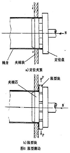
As shown in Fig. 6 (a), the barrel is placed in the flanger, and the positioning discs on both sides move in the middle to clamp the cock; and the plough is pushed into the barrel. When the edge of the bucket is tight with the positioning disc, the positioning disc stops moving. At this time, the clamp barrel block moves along the radial center of the barrel to clamp the barrel body between the clamp barrel core and the clamp barrel block.
As shown in Fig. 6(b), the bulging block expands outward in the radial direction, forcing the barrel edge to be turned outward. The bulging block swells to the highest point, the burring has been basically completed, and then the bulging block is retracted, the nipple block is loosened, the positioning plate is moved to both sides to exit the barrel body, and the barrel of the turned side is pulled out from the lower part.
The principle of the expansion type is that the expansion cone punch is driven by a hydraulic cylinder or a cylinder, and the expansion cone mold is divided into multiple flaps, that is, a swollen block. When the hydraulic cylinder or cylinder drives the cone core, the expansion block outside the core is expanded to force the barrel body to form; the core is withdrawn, and the expansion piece is retracted due to the spring force.
The expansion type has high efficiency and good quality, but the equipment is more complicated and the structure is larger. At present, this kind of technology is widely used in the burring process of small barrels in China, such as the barrel flange of small square barrels, etc. This method is most suitable.
The expansion type flanging adopts the hydraulic transmission mode, the mechanism is reduced, the work is stable, the force is large, and the effect is excellent.
Four, eccentric rolling flange
This method can better maintain the contour of the flanging, and at the same time adapt to the hot-rolled steel barrel body of the domestic old-fashioned universal welder seam welding. The flanging machine is fed on both sides, and the mechanical cam mechanism is used to control the pressing wheel for flanging. The mechanical cam is driven by the main shaft gear to drive the rotating main shaft and the mechanical cam for intermittent movement. The lift is controlled by the brakes.
5. General technical requirements for the flange of the barrel
The width of the flange of the barrel should meet the requirements of the process size. The flange angle is generally 90°~100°, and the edge width error should not be greater than 0.5-1mm: the flange should be smooth and round, and there should be no cracks or wrinkles. There must be no protruding nozzles, broken edges, etc. at the cuffs.
The rounded corners should not be too large. In general, the fillet radius should not be greater than the thickness of the sheet. Because the rounded corner is too large, the rolled edge will be pushed into the barrel body when the barrel body and the top of the bottom of the barrel are wound, so that the width of the actually used barrel body is smaller than the process requirement and smaller than the original flange width. Therefore, the sealing is not tight and affects the sealing effect of the steel drum.
Down Wipe,Wipe And Down,Best Down Wipe,Down Wipe For Sale
DONGYANG COMEXA SANITARY PRODUCTDS LTD.,CO , https://www.comexawipes.com